Back to the future for a tutorial from 2002 using VB6 and DirectX 8.0!!!
Download final sample code 559k
The absolutely enormous bug tutorial
Well, here we go. It’s time for another huge tutorial. This
one covers DX8 cameras, lights, meshes, animated meshes, vector
and matrix arithmetic, a verlet physics engine, dds textures and
alpha blending….. gasp
Inspiration for bugs
My inspiration for this tutorial was to build a physics engine
after reading a gamasutra article by Thomas Jakobsen of IO
Interactive. The first actual work was to design a model for my
physics entities. I was aiming for some kind of insect.
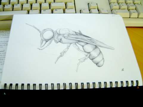
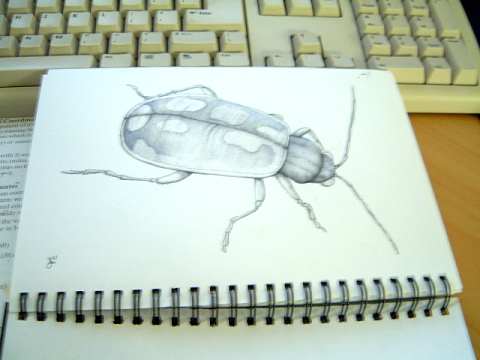
In the end the wasp character looked a bit complex, so I ended
up going for the beetle. The model was constructed using IK
chains to hold the various meshes together. I then key framed
an animation of the legs moving (in my interpretation of a bugs
walk).
Then I made textures from a photograph of some insects.
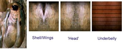
These textures where then applied to the appropriate meshes. I
ended up simply going for a diffuse dark grey for the legs
rather than try and map any textures.
Once that was done I used the DX SDK to convert my mesh file
into a .X file.
Getting started
The good news is that Microsoft have already done a lot of hard
work for you creating a pretty good framework of modules and
classes along with the D3DX library. Overall I found it made
the experience of creating a 3D app pretty painless. Some
explorations of matrix math later on hurt a lot more however : )
The first step was to be able to initialise the DX8 engine and
draw me some lines. The idea is that this will provide the
‘wireframe’ view of all my bouncing boxes once I create the
physics engine.
First I included the files provided by MS. D3danimaition.cls,
d3dframe.cls, d3dinit.bas, d3dmesh.cls, d3dpick.cls,
d3dshader.bas, d3dutil.bas
Then I made a form, pasted on a picture control, and added some
declarations.
Private Type CUSTOMVERTEX
    v As D3DVECTOR
    color As Long
    tu As Single
    tv As Single
End Type
Const D3DFVF_COLORVERTEX = (D3DFVF_XYZ Or D3DFVF_DIFFUSE Or D3DFVF_TEX1)

Dim m_ParticleTexture As Direct3DTexture8
Dim m_VertB As Direct3DVertexBuffer8

Dim m_Verts() As CUSTOMVERTEX
This gives us a texture for the vertexes of our objects
(a Particle texture), a vertex buffer, and a array of vertexes
to fill with data.
From here added a routine to initialise the 3d stuff. Luckily
MS already provide a bunch of stuff in the d3dinit.bas routines,
so it ends up fairly simple..
Private Sub initialiseD3D()

    'setup D3d
    m_binit = D3DUtil_Init(Picture1.hwnd, True, 0, 0, D3DDEVTYPE_HAL, Me)

    'Set up some lights and camera
    g_lWindowWidth = Picture1.ScaleWidth
    g_lWindowHeight = Picture1.ScaleHeight
    D3DUtil_SetupDefaultScene

    'position the camera
    D3DUtil_SetupCamera vec3(0, 60, -300), vec3(0, 60, -200), vec3(0, 1, 0)

    Dim v As CUSTOMVERTEX

    Set m_ParticleTexture = D3DUtil_CreateTexture(g_dev, App.path & "\Particle.bmp", D3DFMT_UNKNOWN)

    Set m_VertB = Nothing
    Set m_VertB = g_dev.CreateVertexBuffer(4 * m_MaxParticles * Len(v), 0, D3DFVF_COLORVERTEX, D3DPOOL_MANAGED)

End Sub
I called this routine from the Form_Load subroutine.
I also added a command button to the page so I could have a way
to get it all started. This is the basic DX8 render loop below.
Private Sub Command1_Click()
        Do


            'Start the Scene
            g_dev.BeginScene

            'clear the buffer
            D3DUtil_ClearAll QBColor(8)

	'DO THE DRAWING HERE….

            'End the scene
            g_dev.EndScene

            'update the screen...
            D3DUtil_PresentAll g_focushwnd

            DoEvents
        Loop Until m_run = False
End Sub
Still nothing much to see though… Against my very visual
development style, the next stop is a physics simulation which
will be temporarily invisible!
Bouncing Verlet boxes
There is heaps of ‘interesting’ literature I reviewed before
deciding where to go with this simulation. Some of the
excellent work by Chris Heckler and Jeff Lander was very useful
as were some more theoretical papers by Baraff, Mirtich, and
Witkin.
My original intention was to perform correct collision detection
and restoration, but I ran out of time in my busy schedule, so
maybe later perhaps : )
So why did I choose Verlet instead of a more traditional ODE
solver? Well I chose it because of its simplicity and
stability. Using the ODE techniques you have to use integration
approximations to work out what the new position of objects will
be after a given timestep. In comparison Verlet implies a known
position before and after the timestep, and it is the velocity
that is an approximation.
To model real 3D objects using verlet, they are built out of
particles with constraints. The constraints I have used are
simply sticks of a given length between the particles. By
arranging them carefully you end up with boxes, pyramids, even
stick figures.
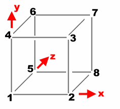
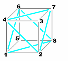
This is the infamous box I am planning on making (could even be
considered a crate). The 8 particles make up its corners, and
12 sticks make up its sides. However it don’t hold up that well
with only these 12 sticks, so we need to add cross bracing… more
like this.
Right time to see how all this hangs together (literally).
Rather than avoid the issue here is the code for the Verlet
integration engine;
'**************************************************
' RIGID BODY PHYSICS SIMULATION
'**************************************************
' David Brebner, Unlimited Realities (2001)
'**************************************************
' Modeled using particles with join
' Thanks to Jakobsen, Baraff, Mirtich, Witkin, Verlet
'
' note : verlet fixed time integration is used in
'        this simulation for stablility
'**************************************************

Public num_particles As Integer

Public num_join As Integer
Public join_p1(1000) As Long
Public join_p2(1000) As Long
Public join_rl(1000) As Long

Public m_curp(1000) As D3DVECTOR
'position right now

Public m_oldp(1000) As D3DVECTOR
'the old position

Public m_forc(1000) As D3DVECTOR
'Force accumulation

Public m_grav As D3DVECTOR
'Gravity

Public m_timeStep As Double
'the time between integrations

Public Function TimeStep()
    'this executed the requirements of the physics
    'simulation for the current timestep

    AccumulateForces

    Verlet

    SatisfyConstraints

End Function

Private Function Verlet()
    Dim i As Integer
    Dim tmp As D3DVECTOR
    'time to increment the positions based on the applied forces
    'during the specified timestep...

    For i = 1 To num_particles

        tmp = m_curp(i)

        m_curp(i).x = (m_curp(i).x * 2 - m_oldp(i).x) + (m_forc(i).x * m_timeStep)
        m_curp(i).y = (m_curp(i).y * 2 - m_oldp(i).y) + (m_forc(i).y * m_timeStep)
        m_curp(i).z = (m_curp(i).z * 2 - m_oldp(i).z) + (m_forc(i).z * m_timeStep)

        m_oldp(i) = tmp

    Next

End Function

Private Function SatisfyConstraints()
    Dim delta As D3DVECTOR
    Dim vscale As Double
    Dim rl As Long

    'constrain the box to the ground..
    For i = 1 To num_particles
        If m_curp(i).y < 0 Then
            'we have hit the ground...
            m_curp(i).y = 0
            m_oldp(i).x = m_oldp(i).x + (m_curp(i).x - m_oldp(i).x) * 0.4
            m_oldp(i).z = m_oldp(i).z + (m_curp(i).z - m_oldp(i).z) * 0.4
        End If
    Next


    'constrain sticks based on there length
    For i = 1 To num_join

        D3DXVec3Subtract delta, m_curp(join_p2(i)), m_curp(join_p1(i))

        rl = join_rl(i) * join_rl(i)
        vscale = rl / (delta.x * delta.x + delta.y * delta.y + delta.z * delta.z + rl) - 0.5

        D3DXVec3Scale delta, delta, vscale

        D3DXVec3Subtract m_curp(join_p1(i)), m_curp(join_p1(i)), delta

        D3DXVec3Add m_curp(join_p2(i)), m_curp(join_p2(i)), delta


    Next


End Function

Private Function AccumulateForces()
    Dim i As Integer
    'All particles are influenced by gravity

    For i = 0 To num_particles

        m_forc(i) = m_grav

    Next

End Function
Hopefully that’s surprisingly little (I was certainly
surprised). The main heartbeat is the Timestep function. It
calls the tree helper functions in turn, AccumulateForces,
Verlet, SatisfyConstraints.
The Accumulate Forces function currently only adds gravity to
each of the points. Eventually this would be used to apply
other external forces like explosions or wind. The Verlet
function performs a simple progressive approximation of the new
position. The position is found by taking the current position,
adding the change in position (current – old), and finally,
adding the distance due to the accumulated forces.
The last step is to satisfy any constraints that have been
established. In this case if any points are falling through the
floor (y < 0). The other constraints are the ‘sticks’. These
constraints are applied to ensure the distance between two
particles is equal to the length of the stick.
To perform this distance manipulation I used the D3DX helper
libraries which have a number of vector manipulation functions
built in. In this case I check the length of the stick by
finding the delta (difference) between the two points on the
stick. This distance may have x, y and z components.
Now a restoration vector is made. This is a scaled version of
the delta vector. The scale will attempt to restore the stick
to its constrained length. To keep things all equal half the
restoration is applied to both ends of the stick.
Bouncing Bits…
I can already imagine the strained attention spans, so as a
compromise to my sanity (and yours) here are some bouncing bits.
Remember that basic render loop. Well we are going to add some
guts to it.
Private Sub Command1_Click()
    Dim a%, cnt As Long
    Dim v As CUSTOMVERTEX
    Dim t As Long

    If m_run = False Then
        m_run = True
        t = GetTickCount - 10
        Do

            m_timeStep = (GetTickCount() - t) / 10000
            t = GetTickCount

            'do a physics engine tick
            TimeStep

            'Start the Scene
            g_dev.BeginScene

            'clear the buffer
            D3DUtil_ClearAll QBColor(8)


            g_dev.SetRenderState D3DRS_ZWRITEENABLE, 1
            g_dev.SetRenderState D3DRS_ZENABLE, 1 'False
            g_dev.SetRenderState D3DRS_ALPHABLENDENABLE, 1

            g_dev.SetRenderState D3DRS_SRCBLEND, D3DBLEND_ONE
            g_dev.SetRenderState D3DRS_DESTBLEND, D3DBLEND_ONE
            g_dev.SetTextureStageState 0, D3DTSS_ALPHAOP, D3DTOP_MODULATE

            g_dev.SetRenderState D3DRS_POINTSPRITE_ENABLE, 1 'True
            g_dev.SetRenderState D3DRS_POINTSCALE_ENABLE, 1

            g_dev.SetTexture 0, m_ParticleTexture

            g_dev.SetStreamSource 0, m_VertB, Len(v)
            g_dev.SetVertexShader D3DFVF_COLORVERTEX


            Dim DWFloat0 As Long
            Dim DWFloat1 As Long
            Dim DWFloatp08 As Long
            DWFloat0 = FtoDW(0.1)
            DWFloat1 = FtoDW(1)
            DWFloatp08 = FtoDW(5)
            ' Set the render states for using point sprites
            g_dev.SetRenderState D3DRS_POINTSIZE, DWFloatp08
            g_dev.SetRenderState D3DRS_POINTSIZE_MIN, DWFloat0
            g_dev.SetRenderState D3DRS_POINTSCALE_A, DWFloat0
            g_dev.SetRenderState D3DRS_POINTSCALE_B, DWFloat0
            g_dev.SetRenderState D3DRS_POINTSCALE_C, DWFloat1

            ReDim m_Verts(m_MaxParticles * 2)


            'Render the corners
            cnt = 0
            For a% = 0 To num_particles - 1
                m_Verts(cnt).v = m_curp(a% + 1)
                m_Verts(cnt).color = &HFFFFFFFF
                cnt = cnt + 1
                If cnt = m_MaxParticles Then
                    D3DVertexBuffer8SetData m_VertB, 0, Len(v) * cnt, 0, m_Verts(0)
                    g_dev.DrawPrimitive D3DPT_POINTLIST, 0, cnt
                    cnt = 0
                End If
            Next
            D3DVertexBuffer8SetData m_VertB, 0, Len(v) * cnt, 0, m_Verts(0)
            g_dev.DrawPrimitive D3DPT_POINTLIST, 0, cnt

            g_dev.SetRenderState D3DRS_POINTSPRITE_ENABLE, 0
            g_dev.SetRenderState D3DRS_POINTSCALE_ENABLE, 0
            g_dev.SetRenderState D3DRS_ALPHABLENDENABLE, 0

            'Render the edges
            cnt = 0
            For a% = 0 To num_join - 1
                m_Verts(cnt * 2).v = m_curp(join_p1(a% + 1))
                m_Verts(cnt * 2).color = &HFFFFFFFF
                m_Verts(cnt * 2 + 1).v = m_curp(join_p2(a% + 1))
                m_Verts(cnt * 2 + 1).color = &HFFFFFFFF
                cnt = cnt + 1
                If cnt = m_MaxParticles Then
                    D3DVertexBuffer8SetData m_VertB, 0, Len(v) * cnt * 2, 0, m_Verts(0)
                    g_dev.DrawPrimitive D3DPT_LINELIST, 0, cnt * 2
                    cnt = 0
                End If
            Next
            'whats left
            D3DVertexBuffer8SetData m_VertB, 0, Len(v) * cnt * 2, 0, m_Verts(0)
            g_dev.DrawPrimitive D3DPT_LINELIST, 0, cnt * 2


            'End the scene
            g_dev.EndScene

            'update the screen...
            D3DUtil_PresentAll g_focushwnd


            DoEvents
        Loop Until m_run = False
    End If
End Sub
Despite the slightly intimidating nature of the code,
it’s really just 3 types of stuff going on.
1)
Calls to our physics engine.
2)
DX3D configuration code. This stuff sets up the render states,
and assigns textures to our points.
3)
Stuffing our vertex buffers full of bouncing points from our
physics simulator, and then rendering the vertex buffer
primitive.
You can try out the sample program to see how it all hangs
together.
Not all graphics cards will display the point lists correctly,
but these are little alpha globes used to mark the points at the
vertex of the objects.
The line list meanwhile should work fine, this is the sticks
which hold the objects together.
Bounding Box
We have our objects, but it’s not really much of a physics
simulation because all our objects simply bounce through each
other. The only collisions are currently performed with the
floor!
The collision detection technique I wanted to use is a plate
method. This essentially treats each face of an object as an
infinite plate extending in all directions. Then by checking
for a combination of collisions of plates between objects you
can determine a collision.
This becomes more difficult as you try and manage edge or point
collisions with a plate, and detecting exactly where the forces
should be applied.
Hence rather than do maths, I have cheated in a very nasty quick
and dirty way!!! We are using my patented ‘Bounding Box
collisions for the maths impared’ technique.
1)
We essentially figure out the biggest box that will enclose our
object.
2)
We check if two bounding boxes touch each other.
3)
We figure out the centre of that box (our fake centre of mass)
4)
We calculate the distance between the centre of mass of the two
objects.
5)
We repulse each other in opposite directions by a fraction of
the distance (the closer they get, the more they are repulsed)
So like I say, not very scientific, but try out the demo and see
the boxes ‘collide’.
To accommodate the bounding box, and the centre of mass, I added
a few new vectors to the body type.
Public Type body_type
    Part_Min As Long
    Part_Max As Long
    Join_Max As Long
    Join_Min As Long

    bound_min As D3DVECTOR
    bound_max As D3DVECTOR

    centre_mass As D3DVECTOR

    mesh As Long
End Type
Now we add the Detect Collisions routine to the main
physics timestep.
Public Function TimeStep()
    'this executed the requirements of the physics
    'simulation for the current timestep

    AccumulateForces
    Verlet
    DetectCollisions
    SatisfyConstraints
End Function
And finally the actual code to detect collisions itself.
As you can see it is fairly simple. Initially working out the
bounding box, and hence the centre of mass.
The routine checks for overlaps, and pushes each point in the
object away from the other by half of the collision force. The
collision force is estimated from the distance of their centre
of masses.
Private Function DetectCollisions()
    'collide with the ground...
    Dim i As Long
    Dim j As Long
    Dim a As Long
    Dim delta As D3DVECTOR

    For i = 1 To num_particles
        If m_curp(i).y < 0 Then
            'we have hit the ground...
            m_curp(i).y = 0
            m_oldp(i).x = m_oldp(i).x + (m_curp(i).x - m_oldp(i).x) * 0.4
            m_oldp(i).z = m_oldp(i).z + (m_curp(i).z - m_oldp(i).z) * 0.4
        End If
    Next

    'first precomputations
    For i = 0 To num_body - 1
        'bounding box
        g_d3dx.ComputeBoundingBox m_curp(body(i).Part_Min), body(i).Part_Max - body(i).Part_Min, D3DFVF_NORMAL, _
body(i).bound_min, body(i).bound_max
        'ridiculously cheap centre of mass
        body(i).centre_mass.x = (body(i).bound_min.x + body(i).bound_max.x) / 2
        body(i).centre_mass.y = (body(i).bound_min.y + body(i).bound_max.y) / 2
        body(i).centre_mass.z = (body(i).bound_min.z + body(i).bound_max.z) / 2
    Next

    'now check all the bodies if their bounding boxes overlap...
    For i = 0 To num_body - 1
        For j = i To num_body - 1
            If (body(i).bound_min.x > body(j).bound_min.x And body(i).bound_min.x < body(j).bound_max.x)
                Or (body(i).bound_max.x > body(j).bound_min.x And body(i).bound_max.x < body(j).bound_max.x) Then
                If (body(i).bound_min.y > body(j).bound_min.y And body(i).bound_min.y < body(j).bound_max.y)
                    Or (body(i).bound_max.y > body(j).bound_min.y And body(i).bound_max.y < body(j).bound_max.y) Then
                    If (body(i).bound_min.z > body(j).bound_min.z And body(i).bound_min.z < body(j).bound_max.z)
                       Or (body(i).bound_max.z > body(j).bound_min.z And body(i).bound_max.z < body(j).bound_max.z) Then
                        'we have a bounding box collision, now examine in more detail...

                        'super bogus for now...

                        D3DXVec3Subtract delta, body(i).centre_mass, body(j).centre_mass
                        D3DXVec3Scale delta, delta, 0.001
                        'delta.x = 0.03 / delta.x
                        'delta.y = 0.03 / delta.y
                        'delta.z = 0.03 / delta.z

                        For a = body(i).Part_Min To body(i).Part_Max
                            'm_curp(a).x = m_curp(a).x - 5
                            D3DXVec3Add m_curp(a), m_curp(a), delta
                        Next
                        For a = body(j).Part_Min To body(j).Part_Max
                            'm_curp(a).x = m_curp(a).x - 5
                            D3DXVec3Subtract m_curp(a), m_curp(a), delta
                        Next
                    End If
                End If
            End If
        Next
    Next

End Function
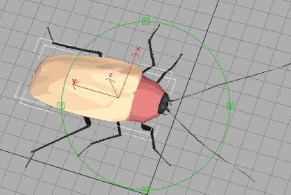
Textured Bugs
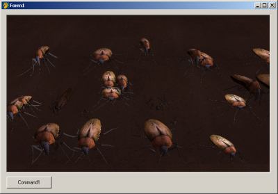
Well physics (even cheap replicas) is pretty cool, but I feel
the need for some bugs. Its time to take the mesh designed at
the start of the tutorial – then get it bouncing along with the
boxes.
It sounds like a simple thing…. and in the end it was simple,
but I spent a lot of time reading text books and looking at
source code before the answer became obvious.
The problem is to create a matrix that will orientate (in this
case rotate) a mesh to line up with a 6 normalised vectors
describing the corners of a box. When I say normalised, this
means they are scaled to 1, and aligned with the origin so that
translation and scaling to not mess up our maths.
After going through all sorts of mathematical torture it became
evident, slightly unbelievably, that it is exactly these vector
values that make up the matrix… as this is basically the proof
of a rotation matrix.
If we consider only three points of the six, which is enough to
form an axis, you can see from this diagram how they fit into
the matrix.
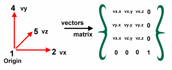
The end result is a rotation matrix. We then add the
translation and scaling back to the matrix, and ‘bingo’ we can
reposition our mesh aligned with the points in our physics
engine.
For i = 0 To num_body - 1
                If body(i).Part_Max - body(i).Part_Min = 7 Then

                    p1 = m_curp(body(i).Part_Min)
                    p2 = m_curp(body(i).Part_Min + 1)
                    p4 = m_curp(body(i).Part_Min + 3)
                    p5 = m_curp(body(i).Part_Min + 4)

                    D3DXVec3Subtract vx, p4, p1
                    D3DXVec3Subtract vy, p2, p1
                    D3DXVec3Subtract vz, p5, p1

                    D3DXVec3Normalize vx, vx
                    D3DXVec3Normalize vy, vy
                    D3DXVec3Normalize vz, vz


                    m3.m11 = vx.x
                    m3.m12 = vx.y
                    m3.m13 = vx.z
                    m3.m21 = vy.x
                    m3.m22 = vy.y
                    m3.m23 = vy.z
                    m3.m31 = vz.x
                    m3.m32 = vz.y
                    m3.m33 = vz.z
                    m3.m44 = 1

                    D3DXMatrixTranslation m2, m_curp(body(i).Part_Min).x,
                             m_curp(body(i).Part_Min).y, m_curp(body(i).Part_Min).z

                    D3DXMatrixScaling m, (join_rl(body(i).Join_Min + 1)) * 0.013,
                           (join_rl(body(i).Join_Min)) * 0.04, (join_rl(body(i).Join_Min + 9)) * 0.015

                    D3DXMatrixMultiply m, m, m3
                    D3DXMatrixMultiply m, m, m2

                    m_frame.SetMatrix m
                    m_frame.Render g_dev
                End If
            Next
The next elements of interest is the code which actually
handles the mesh. By using the existing Microsoft mesh class
provided it is reasonably easy.
  'load our mesh...
    Set m_frame = New CD3DFrame
    m_frame.InitFromFile g_dev, App.path + "\bug.x", Nothing, Nothing
This loads a mesh into a frame, then the calls in the
matrix mesh code above (m_frame.SetMatrix m and
m_frame.Render g_dev) actually do the alignment and rendering.
To get some camera control I have also added a quick bit of
camera manipulation. You can see this here;
Private Sub Picture1_MouseDown(Button As Integer, Shift As Integer, x As Single, y As Single)
    dwn% = True
    mx = x
    my = y
End Sub

Private Sub Picture1_MouseMove(Button As Integer, Shift As Integer, x As Single, y As Single)
    If dwn% Then
         ox = ox - (mx - x)
         oy = oy - (my - y)
         mx = x
         my = y
         D3DUtil_SetupCamera vec3(0, 200, (oy)), vec3((ox), 0, 0), vec3(0, 1, 0)
    End If
End Sub

Private Sub Picture1_MouseUp(Button As Integer, Shift As Integer, x As Single, y As Single)
    dwn% = False
End Sub
Shadows
Well things are hotting up. We now have bouncing, colliding
bugs. But with our overhead light, it gets hard to see exactly
where our bugs are. The idea of adding a shadow allows the user
to see intuitively the position of the bug when it is off the
ground.
We essentially cast a spherical shadow from the bugs centre of
mass down to the floor. The size and intensity of the shadow
will vary in proximity to the floor.
'draw a shadow..
            Dim sz As Double
            Dim cl As Long
            ReDim m_Verts(num_body * 6)
            For i = 0 To num_body - 1
                If body(i).Part_Max - body(i).Part_Min = 7 Then 'the primitive is a cube...
                    sz = join_rl(body(i).Join_Min + 1) / Log(body(i).centre_mass.y + 0.01)
                    cl = body(i).centre_mass.y
                    If cl < 100 Then cl = 100
                    If cl > 255 Then cl = 255
                    cl = RGB(cl, cl, cl)
                    'project the surface down the y axis...
                    m_Verts(i * 6 + 0).v.x = body(i).centre_mass.x - sz
                    m_Verts(i * 6 + 0).v.z = body(i).centre_mass.z - sz
                    m_Verts(i * 6 + 0).v.y = 1
                    m_Verts(i * 6 + 0).n.y = 1
                    m_Verts(i * 6 + 0).tu = 0
                    m_Verts(i * 6 + 0).tv = 0
                    m_Verts(i * 6 + 0).color = cl

                    m_Verts(i * 6 + 1).v.x = body(i).centre_mass.x - sz
                    m_Verts(i * 6 + 1).v.z = body(i).centre_mass.z + sz
                    m_Verts(i * 6 + 1).v.y = 1
                    m_Verts(i * 6 + 1).n.y = 1
                    m_Verts(i * 6 + 1).tu = 0
                    m_Verts(i * 6 + 1).tv = 1
                    m_Verts(i * 6 + 1).color = cl

                    m_Verts(i * 6 + 2).v.x = body(i).centre_mass.x + sz
                    m_Verts(i * 6 + 2).v.z = body(i).centre_mass.z + sz
                    m_Verts(i * 6 + 2).v.y = 1
                    m_Verts(i * 6 + 2).n.y = 1
                    m_Verts(i * 6 + 2).tu = 1
                    m_Verts(i * 6 + 2).tv = 1
                    m_Verts(i * 6 + 2).color = cl

                    m_Verts(i * 6 + 3).v.x = body(i).centre_mass.x - sz
                    m_Verts(i * 6 + 3).v.z = body(i).centre_mass.z - sz
                    m_Verts(i * 6 + 3).v.y = 1
                    m_Verts(i * 6 + 3).n.y = 1
                    m_Verts(i * 6 + 3).tu = 0
                    m_Verts(i * 6 + 3).tv = 0
                    m_Verts(i * 6 + 3).color = cl

                    m_Verts(i * 6 + 4).v.x = body(i).centre_mass.x + sz
                    m_Verts(i * 6 + 4).v.z = body(i).centre_mass.z + sz
                    m_Verts(i * 6 + 4).v.y = 1
                    m_Verts(i * 6 + 4).n.y = 1
                    m_Verts(i * 6 + 4).tu = 1
                    m_Verts(i * 6 + 4).tv = 1
                    m_Verts(i * 6 + 4).color = cl

                    m_Verts(i * 6 + 5).v.x = body(i).centre_mass.x + sz
                    m_Verts(i * 6 + 5).v.z = body(i).centre_mass.z - sz
                    m_Verts(i * 6 + 5).v.y = 1
                    m_Verts(i * 6 + 5).n.y = 1
                    m_Verts(i * 6 + 5).tu = 1
                    m_Verts(i * 6 + 5).tv = 0
                    m_Verts(i * 6 + 5).color = cl
                End If
            Next

            g_dev.SetTexture 0, m_ShadowTexture
            g_dev.SetRenderState D3DRS_ALPHABLENDENABLE, 1
            g_dev.SetTextureStageState 0, D3DTSS_ALPHAOP, D3DTOP_SUBTRACT
            g_dev.SetRenderState D3DRS_SRCBLEND, D3DBLEND_SRCALPHA
            g_dev.SetRenderState D3DRS_DESTBLEND, D3DBLEND_INVSRCALPHA
            g_dev.SetVertexShader D3DFVF_COLORVERTEX
            g_dev.SetStreamSource 0, m_VertB, Len(v)
            D3DVertexBuffer8SetData m_VertB, 0, Len(v) * (num_body) * 6, 0, m_Verts(0)
            g_dev.DrawPrimitive D3DPT_TRIANGLELIST, 0, (num_body) * 2
This code sets up the ‘quad’ that is used to draw the
shadow. A quad is simply two triangles that are next to each
other to form a square (4 corners = quad).
The blend colour intensity and size of the quad is determined by
the proximity to the ground.
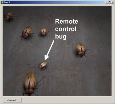
Driving
It’s time to get control of our bugs. There is no fun in a
totally passive simulation. We want to drive our bugs around
our scene to test out our collision algorithms.
To enable us to trap the state of multiple keys, I use a key
array state trick. This works like this;
For any key we can now check if it is currently held
down. The code that the bug actually responds to is in the
check_keys routines. It looks something like this;
Private Sub check_keys()
    Dim v As D3DVECTOR
    Dim v2 As D3DVECTOR
    Dim m As D3DMATRIX
    Dim k As Long
        If keyarray(vbKeyLeft) Then
        D3DXMatrixIdentity m
        D3DXMatrixRotationY m, -10 * m_timeStep
        For k = 1 To 88
            D3DXVec3Subtract v, m_curp(k), body(0).centre_mass
            'v is now relative to the centre of the box
            D3DXVec3TransformNormal v, v, m
            'now put it back
            D3DXVec3Add m_curp(k), v, body(0).centre_mass
            'update the old particle position
            m_oldp(k).x = m_curp(k).x
            m_oldp(k).z = m_curp(k).z
        Next
    End If
    If keyarray(vbKeyRight) Then
        D3DXMatrixIdentity m
        D3DXMatrixRotationY m, 10 * m_timeStep
        For k = 1 To 8
            D3DXVec3Subtract v, m_curp(k), body(0).centre_mass
            'v is now relative to the centre of the box
            D3DXVec3TransformNormal v, v, m
            'now put it back
            D3DXVec3Add m_curp(k), v, body(0).centre_mass
            m_oldp(k) = m_curp(k)
        Next
    End If
    If keyarray(vbKeyUp) Then
        D3DXVec3Subtract v, m_curp(5), m_curp(1)
        D3DXVec3Scale v2, v, -19.9 * m_timeStep
        D3DXVec3Scale v, v, -20 * m_timeStep
        v.y = 0
        v2.y = 0
        If m_curp(1).y > m_curp(2).y Then
            'whoops upside down..
            m_curp(1).y = m_curp(1).y + (m_curp(1).y - m_curp(2).y) / 50
            m_curp(4).y = m_curp(4).y + (m_curp(1).y - m_curp(2).y) / 50
        End If
        For k = 1 To 8
            D3DXVec3Add m_curp(k), m_curp(k), v
            D3DXVec3Add m_oldp(k), m_oldp(k), v2
        Next
    End If
    If keyarray(vbKeyDown) Then
        D3DXVec3Subtract v, m_curp(5), m_curp(1)
        D3DXVec3Scale v2, v, 19.9 * m_timeStep
        D3DXVec3Scale v, v, 20 * m_timeStep
        v.y = 0
        v2.y = 0
        For k = 1 To 8
            D3DXVec3Add m_curp(k), m_curp(k), v
            D3DXVec3Add m_oldp(k), m_oldp(k), v2
        Next
    End If
End Sub
The end result is that the bug moves forward in the
direction the bug is pointing. Pressing the right or left keys
will rotate the bug slightly in that direction.
Camera
Hmm, I was busy trying to knock another bug off the map, and I
ran off-screen. It’s hard to control your bug when you can’t
see it. Definitely time to add camera control.
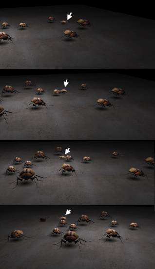
As you can see from the picture, the bug stays on screen, as the
rest of the scene moves around.
In-fact we ended up with 3 camera modes. This one is
camera_mode 2, the far away camera that pans to follow our bug.
This is possibly the simplist. We calculate the vector between
the distant camera and the bug, and then point the camera in
that direction.
In mode 1 we move the camera around to follow the bug. It does
this with a slight delay. This way the camera essentially drags
along behind the bug.
Finally in mode 0 (first bug mode) the camera is always mounted
on the front of our bugs antennae. The hardest part of this was
finding a small enough camera.
Source code;
   'position the camera
            If camera_mode = 0 Then
                'first bug mode...
                D3DXVec3Subtract vec, m_curp(4), m_curp(1)
                D3DXVec3Scale vec, vec, 0.5
                D3DXVec3Add vec_to, m_curp(6), vec
                D3DXVec3Add vec_from, m_curp(2), vec
                D3DUtil_SetupCamera vec_to, vec_from, vec3(0, 1, 0)
            ElseIf camera_mode = 1 Then
                '3rd bug mode
                D3DXVec3Subtract vec, vec_from, body(0).centre_mass
                D3DXVec3Scale vec, vec, 0.25
                D3DXVec3Subtract vec_to, vec_from, vec

                D3DUtil_SetupCamera vec_from, vec_to, vec3(0, 1, 0)

                'animate the vec_from...
                D3DXVec3Normalize vec, vec
                D3DXVec3Scale vec, vec, 60
                D3DXVec3Add vec, body(0).centre_mass, vec
                vec.y = vec.y + 25

                D3DXVec3Lerp vec_from, vec_from, vec, 0.02
            ElseIf camera_mode = 2 Then
                'far away camera...
                vec_from = vec3(0, 120, -400)

                D3DXVec3Subtract vec, vec_from, body(0).centre_mass
                D3DXVec3Scale vec, vec, 0.25
                D3DXVec3Subtract vec_to, vec_from, vec

                D3DUtil_SetupCamera vec_from, vec_to, vec3(0, 1, 0)
            End If
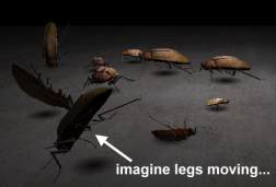
Animation
Potentially the most disconcerting part of the current tutorial
is the way the bugs are simply gliding along on the concrete
floor. It’s time to introduce some animation.
I originally built and exported some basic keyframe animation
for the legs of the bugs.
To reproduce this animation in VB I found a few problems with
some of the class libraries provided, but it all worked out in
the end.
The end result is we load the animation into the frame like so;
'load our mesh...
    Set m_frame = New CD3DFrame
    Set Animation = New CD3DAnimation
    m_frame.InitFromFile g_dev, App.path + "\bug.x", Nothing, Animation
Then we set which animation to use like so;
Animation.SetTime Int(anim) - 0.00005
The end result is by increasing the animation counter we
can proceed to cycle through our animation, and the legs wiggle.
Final
Download final sample code 559k
Well here we go, the final application. I decided to add a nice
‘help screen’ billboard with a bit of alpha-blending to make it
look interesting. (notice how the bug in the bottom left shows
through)
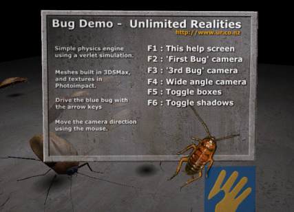
This is drawn using another quad. I should probably put this
into a helper function to save wasting lines of code, but here
it is anyway : )
'draw the help...
            If m_help Then
                g_dev.SetTexture 0, m_HelpTexture

                D3DXMatrixLookAtLH g_viewMatrix, vec3(0, 12, -30),
                  vec3(Cos(t / 1000), 10 + Sin(t / 1000), 0), vec3(0, 1, 0)
                g_dev.SetTransform D3DTS_VIEW, g_viewMatrix

                m_Verts(0).v.x = 10
                m_Verts(0).v.z = -5
                m_Verts(0).v.y = 0
                m_Verts(0).n.z = 1
                m_Verts(0).tu = 1
                m_Verts(0).tv = 1
                m_Verts(0).color = RGB(255, 255, 255)

                m_Verts(1).v.x = -10
                m_Verts(1).v.z = -5
                m_Verts(1).v.y = 0
                m_Verts(1).n.z = 1
                m_Verts(1).tu = 0
                m_Verts(1).tv = 1
                m_Verts(1).color = RGB(255, 255, 255)

                m_Verts(2).v.x = 10
                m_Verts(2).v.z = -5
                m_Verts(2).v.y = 20
                m_Verts(2).n.z = 1
                m_Verts(2).tu = 1
                m_Verts(2).tv = 0
                m_Verts(2).color = RGB(255, 255, 255)

                m_Verts(3).v.x = 10
                m_Verts(3).v.z = -5
                m_Verts(3).v.y = 20
                m_Verts(3).n.z = 1
                m_Verts(3).tu = 1
                m_Verts(3).tv = 0
                m_Verts(3).color = RGB(255, 255, 255)

                m_Verts(4).v.x = -10
                m_Verts(4).v.z = -5
                m_Verts(4).v.y = 0
                m_Verts(4).n.z = 1
                m_Verts(4).tu = 0
                m_Verts(4).tv = 1
                m_Verts(4).color = RGB(255, 255, 255)

                m_Verts(5).v.x = -10
                m_Verts(5).v.z = -5
                m_Verts(5).v.y = 20
                m_Verts(5).n.z = 1
                m_Verts(5).tu = 0
                m_Verts(5).tv = 0
                m_Verts(5).color = RGB(255, 255, 255)


                g_dev.SetRenderState D3DRS_ALPHABLENDENABLE, 1
                g_dev.SetTextureStageState 0, D3DTSS_ALPHAOP, D3DTOP_SUBTRACT
                g_dev.SetRenderState D3DRS_SRCBLEND, D3DBLEND_SRCALPHA
                g_dev.SetRenderState D3DRS_DESTBLEND, D3DBLEND_INVSRCALPHA
                g_dev.SetVertexShader D3DFVF_COLORVERTEX
                g_dev.SetStreamSource 0, m_VertB, Len(v)
                D3DVertexBuffer8SetData m_VertB, 0, Len(v) * 6, 0, m_Verts(0)
                g_dev.DrawPrimitive D3DPT_TRIANGLELIST, 0, 2
            End If